




Pop-Up Visual Indicators Energy Release Verification
 Data Sheet
- Used for energy release verification
- Used on all L-O-X lockout energy isolation valves, and all valves with sensing port
- 316 Stainless Steel version with Nitrile Seals available
ROSS Controls® Pop-Up Indicator
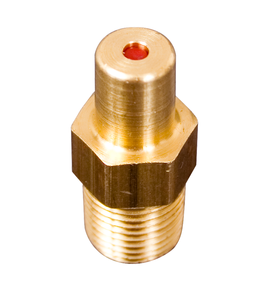
The ROSS® Pop-Up Indicator is a pneumatic energy release verification option device constructed for the industrial environment with a brass body and 1/8” NPT connection. The ROSS® Pop-Up Indicator offers 360° visibility and a redundant verification feature. By pushing on the red plunger, the operator can “feel” the presence of pressure and verify that the indicator is performing its sensing function. Standards suggest that machine design should include a method for verifying the release of energy after lockout.
loading...
loading...
Product Overview
The ROSS Controls Pop-Up Visual Indicator is a pneumatic energy release verification device designed to provide visible confirmation that downstream air pressure has been released following lockout of a pneumatic system. Installed in the sensing port of an L-O-X lockout valve or any ROSS valve equipped with a 1/8 NPT pressure sensing port, the indicator provides a passive, fail-safe visual signal that requires no electrical power.
The 988A30 Pop-Up Indicator uses a spring-loaded red plunger mechanism that extends visibly when downstream pressure is present and retracts flush with the housing when pressure has been exhausted to atmosphere. The 360-degree visibility design allows operators to verify energy release status from any approach angle, supporting OSHA lockout/tagout procedure compliance requirements for energy release verification.
A redundant verification feature enables operators to push the red plunger manually to sense the presence of trapped pressure residually even when the indicator is in its de-pressurized state. This tactile feedback confirms that the indicator mechanism is functioning correctly, addressing the standard requirement for a method to verify that the energy release indicator itself is performing its sensing function.
The standard Series indicator uses a brass body with 1/8 NPT connection, appropriate for general industrial pneumatic applications. A 316 stainless steel version with nitrile seals is available for food processing, pharmaceutical, and chemical environments requiring corrosion-resistant materials. Both versions install directly into the sensing port of compatible ROSS lockout valves without additional hardware.
Key Engineering Features
- Passive Visual Pressure Indication - Spring-loaded red plunger extends when downstream pressure is present and retracts when exhausted to atmosphere, providing a positive visual indication of system energy state without electrical power.
- 360-Degree Visibility - Indicator plunger is visible from all approach angles, allowing energy release status to be confirmed from any viewing position during lockout procedures.
- Redundant Verification Feature - Operators can push the red plunger to physically sense the presence of residual pressure, verifying both the energy release status and the correct functioning of the indicator mechanism itself.
- 1/8 NPT Connection - Standard 1/8 NPT male thread connects directly to the sensing port of ROSS L-O-X lockout valves and other ROSS valves equipped with a 1/8 NPT pressure sensing port.
- Brass Body Construction - Brass body provides corrosion resistance and mechanical durability for general industrial pneumatic environments without contributing to spark hazards in non-hazardous locations.
- 316 Stainless Steel Option - 316 stainless steel body with nitrile seals available for food processing, pharmaceutical, washdown, and corrosive chemical environments requiring elevated material standards.
- No Electrical Power Required - Entirely pneumatic operation requires no wiring, power supply, or electrical connections, eliminating failure modes associated with electrical components in the energy isolation circuit.
- Compatibility with All L-O-X Valve Families - Compatible with all ROSS L-O-X lockout energy isolation valves with sensing ports, including 15 Series modular and classic, 27 Series piloted, and 19 Series soft-start variants.
- OSHA Lockout/Tagout Compliance Support - Addresses OSHA 29 CFR 1910.147 and relevant industry standards that recommend or require a method for verifying the release of pneumatic energy after lockout before authorized personnel perform servicing.
- Compact Installation Profile - Small form factor mounts directly in the valve sensing port without extending beyond the valve envelope in most installation configurations, minimizing additional piping requirements.
Technical Specifications
General Specifications
| Parameter | Specification |
| Model Number (Brass) | 988A30 |
| Model Number (316 SS) | Contact ROSS for stainless steel model |
| Indicator Type | Pop-Up plunger (spring-loaded red) |
| Connection | 1/8 NPT (male) |
| Body Material (Standard) | Brass |
| Body Material (Option) | 316 Stainless Steel |
| Seal Material (316 SS) | Nitrile |
| Valve Compatibility | All non-stainless steel L-O-X lockout valves (988A30); stainless steel L-O-X valves require SS version |
| Operation | Passive pneumatic; no electrical power required |
| Mounting Location | Valve sensing port (Port PV) |
| Visibility | 360 degrees |
| Plunger Color | Red |
Certifications & Compliance
Typical Applications & Industries
Metal Forming and Stamping Press Safety
- Mechanical and hydraulic press pneumatic lockout systems where the L-O-X valve exhausts the press clutch/brake actuator supply. The Pop-Up indicator at the sensing port gives press operators and safety personnel immediate visual confirmation that air supply to the clutch circuit has been fully exhausted before die work.
- Press room lockout/tagout programs that use the Pop-Up indicator as the primary energy release verification device, satisfying OSHA requirements for a method to verify release of energy in the pneumatic circuit.
- Automated stamping line die change procedures where the Pop-Up indicator visible plunger confirms that press pneumatic systems are fully de-energized before tool entry under the ram.
Automotive Body Shop and Assembly
- Pneumatic clamp fixtures and welding positioners using L-O-X lockout valves for maintenance energy isolation. The 360-degree visible indicator allows confined space entry authorization personnel to confirm pressure release from the access path.
- Robotic cell pneumatic lockout procedures where multiple lockout points each have Pop-Up indicators, providing a systematic visual checklist confirmation for the locked-out system state before robot reach envelope entry.
- Assembly line fixture maintenance where Pop-Up indicators on L-O-X valves at each pneumatic circuit allow maintenance technicians to verify all circuits have been de-energized without requiring pressure gauges.
Food and Beverage Processing
- 316 stainless steel Pop-Up indicator versions installed on L-O-X valves in food processing environments where regular washdown with alkaline or acidic sanitizers would corrode brass components. The 316 SS version maintains corrosion resistance and indicator functionality in aggressive cleaning conditions.
- Bottling line filler and capper maintenance lockout where hygienic stainless steel materials are required at all pneumatic components within the splash zone of product and cleaning chemicals.
- Dairy and beverage processing facilities following USDA or EU food safety regulations that specify stainless steel materials for any component in proximity to food contact surfaces.
Pharmaceutical Manufacturing
- Isolator and cleanroom pneumatic system maintenance where validation documentation requires specified material standards for all valve accessories. The 316 SS indicator satisfies material compatibility requirements for pharmaceutical environments.
- Filling line lockout procedures where GMP-compliant energy isolation requires documented verification methods for each locked-out energy source, with the Pop-Up indicator providing the physical verification element.
- Tablet press and capsule filling equipment maintenance where pneumatic lockout systems require visual energy release confirmation before authorized personnel perform die changes or cleaning procedures.
General Industrial Maintenance Programs
- Proactive lockout/tagout program upgrades where existing L-O-X valves without Pop-Up indicators are retrofitted to meet OSHA 1910.147 energy verification requirements. The 988A30 installs directly into the existing sensing port without any modification to the valve or piping.
- Maintenance training programs using the Pop-Up indicator's tactile push-to-sense feature to demonstrate the concept of energy release verification and proper verification procedure to new maintenance personnel.
- Multi-energy-source lockout procedures where pneumatic, electrical, and hydraulic energy sources must all be verified before work can proceed, with the Pop-Up indicator providing the pneumatic system verification element.
Ordering and Model Number Configuration
Standard brass Pop-Up Indicator: model 988A30, 1/8 NPT port threads.
For stainless steel L-O-X lockout valves, a 316 stainless steel Pop-Up Indicator with nitrile seals is available. Contact ROSS for the stainless steel model number.
The 988A30 is compatible with all non-stainless-steel ROSS L-O-X lockout valves with a sensing port. Verify the valve has a 1/8 NPT sensing port (Port PV) before ordering.
For complete lockout valve accessory systems including pressure switch and multiple lockout device, also reference the 95 Series Mechanical Pressure Switches and the 356A30 Multiple Lockout Device.
Pop-Up indicators are commonly ordered as a package with the lockout valve to ensure proper energy release verification from initial installation.
Related Products & Accessories
- 95 Series Mechanical Pressure Switches - Electrical energy release verification switches with DIN EN 175301-803 Form A or M12 connections, providing electronic signal to safety monitoring systems in addition to Pop-Up visual indication. https://www.rosscontrols.com/en/series/95-mechanical-pressure-switches
- 2854 Series Solid State Pressure Sensors - Factory-preset solid-state pressure sensor with M12 connection for electronic status feedback of valve lockout or ready-to-run condition. https://www.rosscontrols.com/en/series/2854-solid-state-pressure-sensor
- L-O-X Lockout Valves 15 Series - Manual lockout and exhaust valves with integrated sensing ports for Pop-Up indicator and pressure switch installation. https://www.rosscontrols.com/en/series/1287-lockout-valves-15-series
- 27 Series Piloted Valves with L-O-X - Piloted inline poppet valves with integrated L-O-X lockout control and sensing ports compatible with Series indicators. https://www.rosscontrols.com/en/series
- 356A30 Multiple Lockout Device - Multiple padlock lockout device for L-O-X valve lockout holes, allowing multiple authorized employees to independently lock out a single energy source. https://www.rosscontrols.com/en/series
Frequently Asked Questions (FAQ)
Q: What is the purpose of the Pop-Up Visual Indicator?
A: The Pop-Up Visual Indicator provides passive visual confirmation that downstream pneumatic pressure has been released following lockout of an L-O-X valve or other lockout device. It supports OSHA 29 CFR 1910.147 and ISO 14118 requirements for a method to verify energy release before authorized personnel perform maintenance work on pneumatic systems.
Q: How does the indicator work?
A: The indicator uses a spring-loaded red plunger mechanism. When downstream pressure is present, the air pressure overcomes the spring force and extends the plunger visibly above the housing. When pressure is exhausted, the spring retracts the plunger flush with the housing, providing a positive visual de-pressurized state indication.
Q: What is the redundant verification feature?
A: By pushing the red plunger downward, the operator creates a slight increase in sensing port flow that will be felt as resistance if any residual pressure remains. This push-to-sense function simultaneously verifies: (1) that the plunger mechanism is operating correctly, and (2) that no residual pressure is trapped downstream of the indicator. It addresses the requirement that machine design include a method for verifying the indicator is performing its sensing function.
Q: Which L-O-X valve series are compatible with the 988A30?
A: The 988A30 is compatible with all ROSS L-O-X lockout valves that have a 1/8 NPT sensing port (Port PV). This includes 15 Series Classic and Modular, 27 Series Piloted with L-O-X, and 15 Series L-O-X with EEZ-ON soft-start models in non-stainless steel construction. The 316 stainless steel Pop-Up Indicator is required for stainless steel L-O-X valve variants.
Q: Can the Pop-Up Indicator be installed on non-ROSS valves?
A: Yes. Any valve with a 1/8 NPT port connected to the downstream pressure zone can accept the 988A30 Pop-Up Indicator. The indicator reads the pressure at whatever port it is installed in, which must reflect the downstream system pressure for correct energy release verification.
Q: Does the indicator require any maintenance?
A: Maintenance is minimal. Inspect the plunger quarterly to confirm it moves freely without sticking. If the plunger becomes sluggish due to contamination, the indicator may not fully extend under low-pressure conditions. Replace the indicator if the plunger does not move freely or if the housing is physically damaged.
Q: Is the Pop-Up Indicator approved for use in hazardous locations?
A: The standard 988A30 is not classified for hazardous (classified) locations. For pneumatic lockout applications in explosive atmospheres, consult ROSS Controls for appropriate energy isolation equipment certified for the hazardous area classification.
Q: Can I install the indicator in a vertical or horizontal port orientation?
A: The indicator is designed to function in any orientation. However, mounting positions where the plunger extends downward may be affected by gravity in very low-pressure sensing applications. For best visibility, orient the indicator so the plunger extends in a direction that is clearly visible to personnel approaching the locked-out machine.
Q: Does the indicator give any indication of the pressure level?
A: No. The 988A30 is a go/no-go indicator that shows whether pressure above the actuation threshold is present or absent. It does not provide quantitative pressure measurement. For quantitative pressure monitoring, use the 95 Series Mechanical Pressure Switch or 2854 Series Solid State Pressure Sensor for electronic monitoring integration.
Q: What is the pressure threshold at which the plunger extends?
A: The Pop-Up indicator plunger extends when downstream pressure exceeds a low threshold consistent with the spring pre-load. The indicator is designed to be sensitive enough to detect residual trapped pressure in normally de-pressurized pneumatic systems. The actual threshold pressure is documented in the ROSS 988A30 data sheet available from rosscontrols.com.
Q: Is the 316 stainless steel version electrically equivalent to the brass version?
A: Yes. The 316 stainless steel Pop-Up Indicator provides identical visual indication and verification functionality to the brass 988A30. The only difference is the body material and the addition of nitrile seals for chemical resistance. Operational behavior, plunger mechanics, and connection type are the same.
Q: Can the indicator be used as the sole lockout verification method?
A: OSHA and applicable standards require a complete lockout procedure including application of lockout devices to energy isolation points in addition to energy release verification. The Pop-Up indicator provides the energy release verification step of the procedure; it does not replace application of lockout devices, personal padlocks, or documentation requirements of a written lockout/tagout program.
Installation & Maintenance Guidelines
- Install the 988A30 directly into the 1/8 NPT sensing port (Port PV) of the L-O-X valve. The sensing port connects to the downstream side of the valve poppet, reflecting the downstream pressure state.
- Tighten the NPT connection with a wrench to ensure leak-free sealing. Pipe thread sealant compatible with compressed air service may be used if required.
- Position the installed indicator so the plunger travel direction is visible from the machine access path. Avoid installing in recessed pockets where plunger extension cannot be observed.
- After installation, verify correct function by: (1) pressurizing the system and confirming plunger extends; (2) locking out the valve and confirming plunger retracts fully as pressure exhausts; (3) push-testing the plunger to verify correct spring return and absence of residual pressure.
- Inspect Pop-Up indicator visually at regular maintenance intervals to ensure plunger moves freely and the housing is not damaged by impact or corrosion.
- For 316 SS versions, no additional protection is required in washdown environments. Avoid impact damage that could distort the indicator body or bind the plunger mechanism.
Warranty & Global Support
ROSS Controls provides a one-year warranty on all Series Pop-Up Visual Indicators, covering defects in material and workmanship from date of purchase.
Contact ROSS Controls Customer Service at 1-800-GET-ROSS or Technical Service at 1-888-TEK-ROSS for product specifications, compatibility verification, and replacement parts.
The 988A30 data sheet and installation instructions are available at rosscontrols.com.
Download Catalog: https://www.rosscontrols.com/en/series/94-pop-up-visual-indicators
Download Documents
Pop-Up Visual Indicators
