Mechanical Pressure Switches Electrical Status Indication or Energy Release Verification
- May be installed on all L-O-X® valves and L-O-X® valves with EEZ-ON® function with pressure sensing port
- Provides a means to verify the release of downstream pressure to next obstruction
- Factory preset
ROSS Controls® Pressure Switches
The ROSS® Pressure Switches are electrical energy release verification option devices. The ROSS® Pressure Switch offers an electronic pressure sensing option that can be integrated into a safety monitoring system, which confirms energy isolation throughout the circuit. Standards suggest that machine design should include a method for verifying the release of energy after lockout.
loading...
loading...
Product Overview
The ROSS Controls mechanical pressure switches are electrical energy release verification devices that provide a hardwired signal to safety monitoring and control systems indicating the downstream pressure status of a pneumatic lockout valve circuit. When installed in the 1/8 NPT sensing port of an L-O-X lockout valve or downstream piping, these switches close an electrical circuit on falling pressure, signaling to a safety relay, PLC, or monitoring system that downstream air pressure has been exhausted.
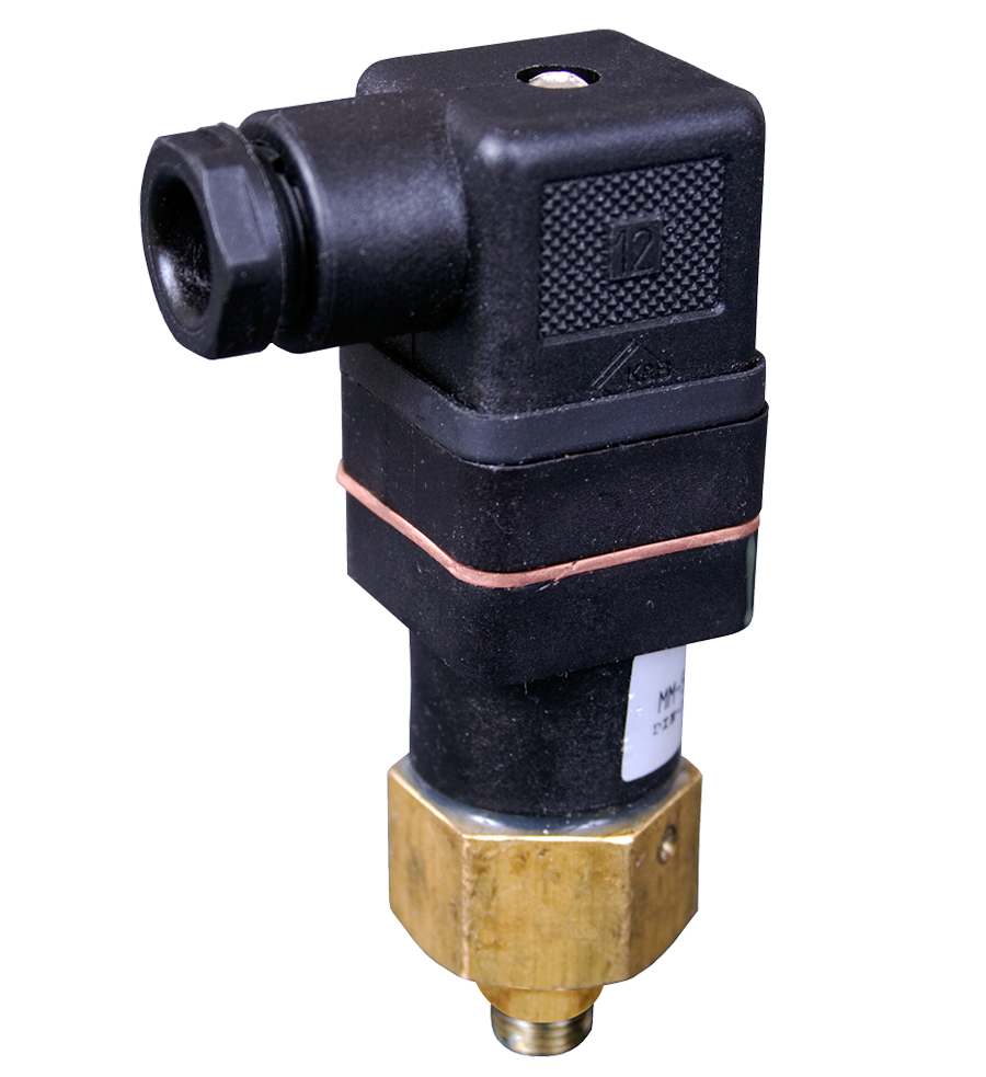
Two primary model configurations are offered: the 586A86 with a DIN EN 175301-803 Form A connector (standard solenoid-type connector) and the 1153A30 with an M12 connector. Both models are factory preset and close on falling pressure, with the 586A86 closing at 5 psig (0.34 bar) and the 1153A30 closing at 22 psig (1.5 bar) falling. The M10 port thread on the 1153A30 model provides a compact mounting interface directly in the valve sensing port.
The Series also includes the 798E30 DPDT (Double-Pole Double-Throw) pressure switch with nitrile seals for applications requiring redundant electrical contacts, such as safety relay circuits that use both normally-open and normally-closed contacts for cross-monitoring and diagnostics. The 798E30 is factory preset at 5 psi falling and provides two independent switching circuits from a single pressure sensing installation.
For complete energy release verification system designs, the series pressure switches are used in conjunction with the 94 Series Pop-Up Visual Indicator, with the pressure switch providing the electronic signal to the machine safety monitoring system and the Pop-Up indicator providing the passive visual confirmation for operator verification.
Key Engineering Features
- Factory Preset Switching Point - All Series models are factory preset and calibrated, requiring no field adjustment. The 586A86 closes at 5 psig (0.34 bar) falling; the 1153A30 closes at 22 psig (1.5 bar) falling. Field-adjustable versions also available.
- Closes on Falling Pressure - Switch transitions from open to closed as pressure drops through the preset threshold, signaling to the control system when downstream pressure has fallen to the safe de-energized level.
- DIN EN 175301-803 Form A Connection (586A86) - Standard DIN solenoid connector interface on the 586A86 model allows use of 91 Series DIN connectors for wiring integration, maintaining consistent connector types across valve accessories.
- M12 Connection (1153A30) - The 1153A30 uses an M12 connector for integration with safety PLCs and I/O modules that use M12 industrial standard connections, eliminating adapter requirements in M12-based wiring architectures.
- DPDT Configuration (798E30) - Double-Pole Double-Throw 798E30 pressure switch provides two independent contact sets (normally open and normally closed) for safety relay cross-monitoring circuits and diagnostic applications requiring both contact states.
- 1/8 NPT Sensing Port Connection - The 586A86 installs via standard 1/8 NPT threads into any L-O-X valve sensing port or downstream pressure tap. The 1153A30 uses an M10 port connection for direct valve sensing port mounting.
- Nitrile Seals - Nitrile seal construction provides compatibility with standard compressed air and petroleum-based lubricants across the ambient and media temperature range of pneumatic lockout valve applications.
- Safety System Integration - Electrical output enables integration of pneumatic energy release status into safety relay, safety PLC, or monitoring controller circuits, supporting IEC 62061 and ISO 13849 safety function architectures.
- Compatibility with All L-O-X Valve Families - Compatible with all ROSS L-O-X lockout valves with sensing ports across the 15 Series, 27 Series, and L-O-X with EEZ-ON product families.
- Compact Housing Dimensions - Small housing dimensions allow installation in the valve sensing port with minimal protrusion beyond the valve body envelope, reducing installation footprint in congested machine cabinets.
Technical Specifications
General Specifications
| Parameter | Specification |
| Switch Type | Electromechanical pressure switch |
| Switch Action | Closes on falling pressure (normally open at system pressure) |
| 586A86 Model - Connection | DIN EN 175301-803 Form A |
| 586A86 Model - Port Thread | 1/8 NPT |
| 586A86 Model - Factory Preset | 5 psig (0.34 bar) falling |
| 1153A30 Model - Connection | M12 |
| 1153A30 Model - Port Thread | M10 x 1 |
| 1153A30 Model - Factory Preset | 22 psig (1.5 bar) falling |
| 798E30 Model - Contact Type | DPDT (Double-Pole Double-Throw) |
| 798E30 Model - Seals | Nitrile |
| 798E30 Model - Factory Preset | 5 psig falling |
| Contact Rating (Solenoid-connected types) | 0.1 A at 125/250 VAC; 0.1 A at 30 VDC; 0.3 A at 60 VDC |
| Mounting Location | Valve sensing port or downstream pressure tap |
Certifications & Compliance
Typical Applications & Industries
Safety-Monitored Machine Lockout Systems
- Press rooms with safety PLCs monitoring energy isolation status across multiple L-O-X valve stations. The 586A86 pressure switch at each lockout point provides a discrete input signal to the safety PLC confirming downstream pressure has been exhausted before allowing maintenance mode access permissions.
- Robotic cell energy isolation systems where ISO 13849-compliant safety functions require documented feedback from each pneumatic lockout point. The normally-closed contact of the 586A86 switching at the preset 5 psig threshold provides the feedback signal for safety function monitoring.
- Multi-station transfer line lockout where a safety relay panel monitors all lockout valve pressure switches simultaneously, requiring positive indication from every switch before enabling the 'safe to enter' signal.
Hydraulic and Pneumatic Press Control
- Mechanical press pneumatic clutch/brake circuit monitoring where the series pressure switch on the L-O-X valve sensing port signals to the press safety control system that the clutch air supply circuit has been fully exhausted during a die change lockout.
- Hydraulic press intensifier circuits controlled by pneumatic valves where pressure switch feedback confirms de-energization of hydraulic pressure through the pneumatic lockout valve air pilot circuit.
- Press brake and power shear pneumatic lockout systems that require electrical confirmation of safe state before the blade safety barrier permits access to the blade zone.
DM2 Series Double Valve Status Monitoring
- DM2 Series C double valve installations requiring status indicator feedback to the safety controller via the dedicated status indicator sensing port. The mechanical pressure switch Y670B94 (DIN EN 175301-803 Form A connection, 22 psig falling preset) is factory-designed for this application and is specified by the DM2 Series C status indicator code.
- Safety function diagnostics in Category 4, PLe press control systems where status indicator feedback from the pressure switch is used for cross-monitoring of the two valve element outputs.
- Safety exhaust systems where positive verification of pressure release after valve actuation is required by the safety control architecture and must be transmitted to the safety relay or safety PLC.
Food Processing and Pharmaceutical Equipment
- Hygienic machine lockout systems in food processing facilities where the M12 connector interface of the 1153A30 integrates with the M12-based field bus wiring standards used in modern food machinery.
- Pharmaceutical tableting and encapsulation equipment where lockout/tagout programs are part of GMP-validated procedures and electrical confirmation of pressure release supports the validation documentation trail.
- CIP (Clean-In-Place) system isolation valve monitoring where the pressure switch signals to the process control system that the pneumatic actuator supply circuit is isolated during cleaning cycle setup.
Building Integrated Safety Systems
- Area safety light curtain and gate interlock systems integrated with pneumatic press safeguarding where the pressure switch on the main air supply L-O-X valve provides confirmation that the pneumatic energy source is isolated when the safety gate is open.
- Safety relay-based machine control panels where DPDT pressure switch (798E30) contacts are connected to both safety relay input channels for cross-monitoring that the relay's normally-open and normally-closed input channels receive opposite states as expected.
- Two-hand control system integration where pressure feedback from the series switch is used as part of the mute condition for safety light curtains during normal press cycle entry, confirming the press ram is fully de-energized.
Energy Industry and Utilities
- Compressor station isolation valve monitoring where pressure switches on pneumatic lockout valves provide SCADA system signals confirming that sections of the compressed air distribution system have been positively isolated.
- Turbine control system pneumatic valve monitoring where the pressure switch feeds back valve actuation confirmation to the DCS, supporting control system diagnostics and maintenance monitoring functions.
- Nitrogen purge system pneumatic lockout verification in gas processing facilities where isolated section confirmation requires electrical feedback to the control room monitoring system.
Ordering and Model Number Configuration
586A86: DIN EN 175301-803 Form A connection, 1/8 NPT port, factory preset at 5 psig (0.34 bar) falling. For use with standard 91 Series DIN connectors.
1153A30: M12 connection, M10 x 1 port thread, factory preset at 22 psig (1.5 bar) falling. For integration with M12 wiring systems and safety PLCs with M12 I/O.
798E30: DPDT pressure switch with nitrile seals, factory preset at 5 psig falling. Specify connection type when ordering (DIN EN 175301-803 Form A or other). For safety relay cross-monitoring requiring both normally open and normally closed contacts.
RC026-13: Redundant downstream feedback switch assembly, 3/8 NPT port, DIN EN 175301-803 Form A connection, factory preset at 5 psig (0.3 bar) falling. Used for dual electrical verification of downstream pressure.
The DM2 Series C status indicator Y670B94 (DIN EN 175301-803 Form A, 22 psig falling) is the designated status indicator model for DM2 Series C valve stations. Order separately or as part of the valve configuration.
For pressure switch connectors (EN 175301-803 Form A), use 91 Series connector 586A86-compatible connectors. For the 1153A30 M12 switch, use standard M12 cables from the 93 Series.
Related Products & Accessories
- 94 Series Pop-Up Visual Indicators - Passive pneumatic visual indicator for energy release verification, used in conjunction with Series pressure switches for complete verification systems. https://www.rosscontrols.com/en/series/94-pop-up-visual-indicators
- 2854 Series Solid State Pressure Sensors - Solid-state M12-connected pressure sensor for electronic status feedback of valve lockout or ready-to-run condition, complementing mechanical pressure switches in modern safety architectures. https://www.rosscontrols.com/en/series/2854-solid-state-pressure-sensor
- 91 Series Electrical Connectors - DIN EN 175301-803 Form A connectors compatible with the 586A86 pressure switch for field wiring connections. https://www.rosscontrols.com/en/series/91-electrical-connectors
- L-O-X Lockout Valves 15 Series - Primary valve family for which Series pressure switches provide sensing port energy release verification. https://www.rosscontrols.com/en/series/1287-lockout-valves-15-series
- 93 Series Preassembled Wiring Kits - Complete wiring assemblies for DM2, SV27, and M35 Series valve stations including status indicator wiring. https://www.rosscontrols.com/en/series/93-preassembled-wiring-kits
Frequently Asked Questions (FAQ)
Q: What is the difference between the 586A86 and the 1153A30 pressure switches?
A: Both are factory-preset mechanical pressure switches for energy release verification on ROSS L-O-X valves. The 586A86 uses a DIN EN 175301-803 Form A connector and 1/8 NPT port thread, preset to close at 5 psig (0.34 bar) falling. The 1153A30 uses an M12 connector and M10 x 1 port thread, preset at 22 psig (1.5 bar) falling. Select based on the wiring system connector type and which valve sensing port thread is available.
Q: What does 'closes on falling pressure' mean?
A: The switch is normally open when the system is pressurized. As pressure drops below the preset threshold (5 psig for 586A86, 22 psig for 1153A30), the switch contacts close, generating the electrical signal that indicates low/no pressure in the downstream circuit. This action convention - closing the circuit when safe (low pressure) - is commonly used in safety circuit logic where a closed contact confirms the safe state.
Q: Can the preset pressure be adjusted in the field?
A: The 586A86 and 1153A30 are factory preset and are not designed for field adjustment. If a different switching point is required, contact ROSS Controls to determine if an alternate preset option is available for the specific application.
Q: Why does the 1153A30 have a higher preset (22 psig) than the 586A86 (5 psig)?
A: The two models have different preset values by design to suit different application requirements. The 586A86 at 5 psig provides confirmation that downstream pressure has been nearly fully exhausted. The 1153A30 at 22 psig (1.5 bar) is calibrated to the switching point used in the DM2 Series C status indicator application and for valve states where a higher threshold is appropriate for positive indication. The Y670B94 DM2 status indicator switch is also preset at 22 psig (1.5 bar) falling.
Q: What is the contact rating for the series pressure switches?
A: Contact ratings for solenoid-connection type pressure switches are 0.1 A maximum at 125/250 VAC; 0.1 A maximum at 30 VDC; and 0.3 A maximum at 60 VDC. These are sensing-level current ratings suitable for safety relay inputs and PLC discrete inputs but not for directly switching solenoid valve coils or other high-current loads.
Q: What is the 798E30 DPDT pressure switch used for?
A: The 798E30 DPDT (Double-Pole Double-Throw) pressure switch provides two independent switching circuits from one pressure sensing point. This is used in safety relay architectures that require cross-monitoring of both normally-open and normally-closed contacts from the same sensor, providing a means to detect contact welding or failure by verifying that both contacts change state simultaneously at the pressure threshold.
Q: Can I use the series pressure switch to replace a Pop-Up Visual Indicator?
A: No. The Pop-Up Visual Indicator (94 Series) and the Mechanical Pressure Switch (Series) serve complementary functions. The Pop-Up indicator provides passive visual confirmation for personnel physically present at the valve. The pressure switch provides an electrical signal to the control or monitoring system. ROSS recommends using both: the Pop-Up indicator for operator visual verification and the pressure switch for safety system monitoring.
Q: How does the pressure switch integrate into an ISO 13849 safety architecture?
A: The pressure switch feedback signal is used as a diagnostic input to safety relay or safety PLC monitoring circuits. In a safety function design, the switch confirms that the safe state (pressure exhausted) has been achieved after the lockout valve is activated. This feedback supports the diagnostic coverage calculations required for Category 2 and Category 3 safety architectures per ISO 13849-1.
Q: Can the pressure switch be installed in the downstream piping rather than the valve sensing port?
A: Yes. The 586A86 with 1/8 NPT threads can be installed in any downstream pressure tap between the lockout valve and the actuator being isolated. Installing downstream of the valve and piping provides verification that the complete circuit including piping is de-pressurized rather than just the valve downstream port.
Q: What is the RC026-13 redundant downstream feedback switch?
A: The RC026-13 is a dual-circuit pressure switch assembly with a 3/8 NPT port and DIN EN 175301-803 Form A connection, factory preset at 5 psig (0.3 bar) falling. It provides two independent electrical verification circuits from a single downstream installation point, suitable for redundant safety monitoring architectures where dual electrical confirmation is required.
Q: Are replacement connectors available for the 586A86?
A: Yes. The 586A86 uses a standard DIN EN 175301-803 Form A connector opening. Any compatible Form A connector from the 91 Series, including the 937K87 (connector only, no light) or lighted versions 936K87-W (24 VDC) or 936K87-Z (120 VAC), can be used.
Q: What is the difference between the standard Series switches and the Y670B94/Y766B94 DM2 status indicator assemblies?
A: The Y670B94 and Y766B94 are designated status indicator assemblies specifically designed for DM2 Series C valve stations and are specified within the DM2 Series ordering table as status indicator options. They use the same underlying pressure switch technology but are packaged and calibrated for the DM2 sensing port dimensions and the DM2 status indication switching point of 22 psig (1.5 bar) falling. The 586A86 and 1153A30 are general-purpose models for use with the broader L-O-X valve product family.
Installation & Maintenance Guidelines
- Install the 586A86 by threading the 1/8 NPT port directly into the L-O-X valve sensing port (Port PV). Apply thread sealant compatible with compressed air service.
- For the 1153A30, thread the M10 x 1 port into the designated M10 sensing port on compatible ROSS valves. Verify the valve sensing port accepts M10 thread before installation.
- Route electrical cables from the DIN connector or M12 connector to the safety monitoring system, maintaining minimum 2-inch separation from high-voltage power cables.
- Connect the switch contacts per the EN 175301-803 or M12 pin assignments. Pin 1 (Common), Pin 2 (NC), Pin 4 (NO) for EN; verify M12 pinout from 1153A30 data sheet.
- Verify switch operation after installation: (1) with system pressurized above preset, measure open-circuit resistance across NC contacts; (2) lock out valve and exhaust downstream; (3) confirm NC contacts close as pressure falls through the preset threshold.
- For DPDT 798E30 in safety relay cross-monitoring applications, connect normally-open contacts to one relay input channel and normally-closed contacts to the second channel, verifying both channels receive the expected state change at pressure threshold.
- Document the pressure switch model number, preset value, port location, and connection type in the machine safety documentation for ISO 13849 or IEC 62061 validation records.
Warranty & Global Support
ROSS Controls provides a one-year warranty on all Series Mechanical Pressure Switches, covering defects in material and workmanship from date of purchase.
Technical support for pressure switch selection and safety system integration is available at Technical Service: 1-888-TEK-ROSS or Customer Service: 1-800-GET-ROSS.
Data sheets with complete electrical ratings, dimensions, and installation instructions are available at rosscontrols.com.
Download Catalog: https://www.rosscontrols.com/en/series/95-mechanical-pressure-switches
Download Documents
Mechanical Pressure Switches
