HBH HBH Series
- Each single valve in the HBH Series system is equipped with inductive position switches.
- Monitoring of these switches is to be done by an electrical safety control system.
- Poppet-type cartridge valve elements for blocking flow and stopping cylinder motion. Solenoid pilot valves are spool type.
- Special tamper resistant tool required for disassembly
- In-line mounting with Code 62 Flange ports
loading...
loading...
Product Overview
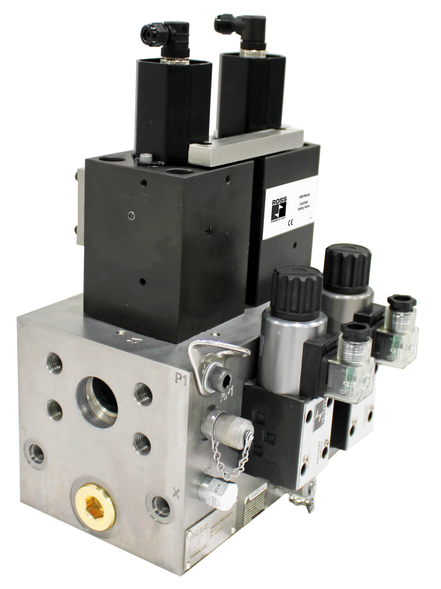
The ROSS Controls HBH Series is a family of redundant hydraulic valve systems designed for critical applications where safe block and stop is required for hydraulically controlled cylinders. Unlike block and bleed systems that vent downstream energy, the HBH Series blocks flow in both directions at the valve, stopping cylinder motion and holding the cylinder in position in the event of loss of supply pressure and/or electrical power, including the ability to hold a vertical load under gravity.
The HBH Series uses poppet-type cartridge valve elements as the primary blocking mechanism, which provide positive sealing and near-zero internal leakage for load holding. The solenoid pilot valves that control the poppet cartridges are spool type. Each single poppet-type valve element is equipped with inductive position switches for real-time monitoring by an external electrical safety control system, enabling the verification of valve state required for Category 4 / PL e safety architectures.
Two body sizes are available: D25 (ISO D25 envelope) handling flows from 0 to 90 gpm with 1-1/2 or 2 Code Flange ports, and D32 (ISO D32 envelope) handling flows from 0 to 145 gpm with 2 Code Flange ports. Both sizes mount in-line using Code Flange ports and are oriented with the solenoid pilot valve assembly accessible for maintenance. The tamper-resistant design requires a special tool for disassembly, protecting the integrity of the safety system.
The HBH valve system uses solenoid pilot operated actuation for both body sizes. Solenoids must be operated synchronously, and both must be energized to permit cylinder motion. Upon de-energization of either solenoid, the poppet cartridge elements close, blocking flow and holding the cylinder load. This architecture ensures that any single failure drives the system to the safe (blocked) state.
Key Engineering Features
- Poppet-Type Cartridge Blocking Elements - Primary blocking function uses poppet-type cartridge valve elements rather than spools. Poppet seats provide positive sealing and dramatically lower internal leakage compared to spool valves, enabling reliable hydraulic load holding in vertical and gravity-loaded cylinder applications.
- Redundant Dual-Valve Architecture with External Monitoring - Two independent poppet-type valve elements equipped with inductive position switches (one per element) allow an external safety control system to verify that both elements are in the correct (blocked or unblocked) position, supporting Category 4 / PL e machine safety architectures per ISO 13849-1.
- Load Holding Capability - The poppet-type construction holds a vertical load in position even if hydraulic supply pressure is lost or electrical power is interrupted. This is essential for overhead and vertical cylinder applications where gravity-loaded actuators must remain stationary during safe access.
- High Flow Capacity - D25 body size handles up to 90 gpm and D32 handles up to 145 gpm, covering the largest hydraulic actuator circuits found in heavy industrial machinery such as die casting machines, large presses, and heavy-load transfer systems.
- Code Flange Ports - High-pressure Code Flange port connections on both D25 and D32 body sizes provide leak-free connections rated for the full 5000 psi operating pressure, eliminating the thread engagement variability of SAE straight-thread fittings on large port sizes.
- Solenoid Pilot Operation - Both D25 and D32 body sizes use solenoid pilot operated actuation to generate the forces required to shift the poppet cartridge elements against full system pressure and flow forces, ensuring reliable actuation under all operating conditions.
- IP65 Solenoid Enclosure - Solenoids are rated for continuous duty per VDE 0580 with EN 175301-803 Form A connections and IP65 enclosure rating, providing dust-tight protection and resistance to fluid splash in hydraulic machine environments.
- Tamper-Resistant Design - Special tamper-resistant tool required for valve disassembly prevents unauthorized personnel from modifying or bypassing the safety system, maintaining compliance with applicable machine safety standards throughout the service life of the equipment.
- Buna-N Seals for Broad Fluid Compatibility - Buna-N (nitrile) seals throughout the valve system provide compatibility with mineral oil HLP and vegetable oil HETG hydraulic fluids across the recommended operating temperature range.
- Ductile Iron Manifold Construction - Valve body and manifold constructed from ductile iron with steel internal components, providing the structural integrity required for sustained 5000 psi service and resistance to the mechanical loads and vibration present in large hydraulic machinery.
Technical Specifications
General Specifications
| Parameter | Specification |
| Safety Function | Block & Stop (Load Holding) |
| Valve Type | Directional Control |
| Construction | Poppet-Type Cartridge Elements (blocking); Spool (solenoid pilot) |
| Actuation | Solenoid Pilot Operated, Spring Return |
| Mounting | Base Mount; any orientation, preferably horizontal |
| Port Type | Code Flange |
| Monitoring | External (by electrical safety control system) |
| Standard Voltage | 24 VDC |
| Duty Cycle | Continuous Duty |
| Solenoid Connection Type | EN 175301-803 Form A |
| Solenoid Enclosure Rating | IP65 per DIN 40050 |
| Inductive Position Switch Type | PNP, M12 5-pin A-coded (2 per system) |
| Switch Current Consumption (Max) | 400 mA per switch |
| Maximum Operating Pressure | 5000 psi (344 bar) |
| Flow Media | Mineral Oil HLP, HL-DIN 51524; Vegetable Oil HETG - VMDA 24568 |
| Valve Body & Manifold Material | Ductile Iron |
| Spool Material | Steel |
| Seal Material | Buna-N |
Temperature Ratings
Recommended operating temperature ranges for the HBH Series valve system.
| Configuration | Ambient Temperature | Media Temperature |
| Ambient Temperature | 4 to 160 F (-20 to 71 C) | |
| Media (Hydraulic Fluid) Temperature | 4 to 140 F (-20 to 60 C) |
Important: Hydraulic fluid viscosity must remain within the valve design range across the full operating temperature envelope. Fluid that is too viscous at cold start or too thin at elevated temperatures can affect poppet cartridge and spool response time.
Flow Performance Data
Flow capacity, port sizes, and weights by body size. Both sizes rated to 5000 psi maximum operating pressure.
| Body Size | Port Size | Flow Rate | Power (each solenoid) | Weight lb (kg) |
| D25 | 1-1/2 Code Flange (682F) or 2 Code Flange (692F) | 0 to 90 gpm | 30 watts | 112.3 (50.9) |
| D32 | 2 Code Flange (792F) | 0 to 145 gpm | 30 watts | 142.8 (64.8) |
Certifications & Compliance
| Certification/Standard | Detail |
| Safety Architecture | Designed for external monitoring. When integrated with a Category 4 / PL e rated external safety control system, enables the highest machine safety performance levels per ISO 13849-1 and IEC 61508. |
| Functional Safety Design Intent | Redundant dual-valve architecture with independent poppet elements and position monitoring supports SIL 3 / Category 4 / PL e safety architectures when properly integrated into a safety-rated control system. |
| Safety Category Target | Category 4, PL e per ISO 13849-1:2015 when combined with a properly configured external safety control system. Certifications pending on specific models; verify with ROSS Controls. |
| SIL Rating | SIL 3 (IEC 61508) achievable in properly integrated redundant system configuration. Functional safety data (MTTFd, DC, CCF) available from ROSS Controls upon request. |
| Solenoid Standard | Solenoids conform to VDE 0580 for continuous duty rated coils in industrial hydraulic applications. |
| Solenoid Enclosure | IP65 per DIN 40050, providing dust-tight protection and resistance to low-pressure water jets. |
Typical Applications & Industries
Die Casting and Metal Casting
- Die casting machine shot plunger and die closing cylinder circuits where the die must be held in position during metal injection and solidification. The HBH poppet elements maintain the hold force even if hydraulic supply pressure fluctuates.
- Tilt-poured and gravity-cast pouring ladle hydraulic drive circuits where the ladle must be stopped and held at precise pour angles. Load holding capability prevents gravity-induced creep under load.
- Die spray system traverse cylinder circuits requiring safe stop and hold during die inspection or maintenance between shots.
Vertical Press and Platen Operations
- Large hydraulic press platen hold applications where an overhead ram must be positively locked in the elevated position before personnel access to the die area. The poppet-type construction prevents downward creep under gravity load.
- Hot forming press circuits where the upper tooling must be held at a defined height during material loading. The HBH system holds the position despite thermal expansion effects on the hydraulic system.
- Rubber and composite molding press circuits requiring safe hold of the press head during mold change or material insertion operations.
Heavy-Load Transfer and Positioning
- Hydraulic lift table and scissor lift circuits in manufacturing and assembly environments where the platform must be held at a working height with personnel standing on it. The poppet seating provides near-zero leakage load hold.
- Transfer car and hydraulic shuttle hydraulic drive circuits on automated assembly lines where the car must stop and hold position at a work station while operators access the conveyed assembly.
- Overhead gantry hydraulic hoist circuits for workpiece lifting and positioning, where the load must be held at height for extended periods during fixture alignment.
Steel and Heavy Industry
- Large rolling mill housing hydraulic pass-line adjustment cylinders requiring safe stop and hold during roll change operations.
- Ladle handling equipment hydraulic hoist and tilt circuits in steel melt shops, where failure to hold position could result in catastrophic molten metal spill.
- Heavy-duty hydraulic shear and guillotine circuits on steel service centers, where the upper blade must be held in the fully retracted position during material loading and alignment.
- Hydraulic cylinder circuits on continuous casters for strand-guide segment adjustment, requiring safe lock-in position during in-process maintenance.
Forestry and Paper Processing
- Large log saw and bucking saw hydraulic feed and clamping circuits where the saw carriage must be stopped and held during blade change or jam clearing.
- Paper reel crane hydraulic circuits where the reel must be held in the elevated position during splice preparation.
Marine and Offshore
- Hydraulic deck crane and lift circuits on marine vessels where personnel work under suspended loads, requiring positive load holding independent of hydraulic supply continuity.
- Offshore platform hydraulic valve actuator circuits where safe isolation and position hold is required before intervention on subsea equipment.
Ordering and Model Number Configuration
The HBH Series model number identifies body size, port size, valve type, material, seal, monitoring, and revision. Select from the D25 and D32 body sizes and corresponding port configurations.
|
HBH Series Model Number Structure:
HBH D XX [Body/Port] B A E X A | | | Series | Body Size / | | Revision Level Port Code | | Communication (X = None) Relief (XX = | Monitoring (E = External) No Relief Valve) | Seal (A = Buna-N) Voltage Valve Type (B = Double) (D = 24 VDC)
Body/Port Codes: 682F = D25 body, 1-1/2 Code Flange 692F = D25 body, 2 Code Flange 792F = D32 body, 2 Code Flange
Example (D25, 1-1/2 flange): HBHDXX682FBAEXB Example (D32, 2 flange): HBHDXX792FBAEXB |
HBH Series is available with 24 VDC solenoids only as standard. Contact ROSS Controls for other voltage requirements.
Both solenoids must be operated synchronously by the external safety control system. De-energization of either solenoid must immediately result in the valve transitioning to the blocked (safe) state.
For D25 body size, specify either 1-1/2 Code Flange (682F) or 2 Code Flange (692F) port configuration.
Contact ROSS Controls for applications requiring fluids other than mineral oil HLP or vegetable oil HETG, pressures above 5000 psi, or flows above 145 gpm.
Accessories
Electrical Connectors for Solenoids
ROSS Controls offers EN 175301-803 Form A prewired connectors compatible with HBH Series solenoid connections. Available in standard and lighted configurations for 24 VDC solenoids.
| Connection | Cord Length | Cord Diameter | Model (No Light) | Model (24 VDC Lighted) |
| EN 175301-803 Form A Prewired (18 AWG) | 2 m (6.5 ft) | 6 mm | 721K77 | 720K77-W |
| EN 175301-803 Form A Prewired (18 AWG) | 2 m (6.5 ft) | 10 mm | 371K77 | 383K77-W |
| Connector for 1/2" Conduit | 723K77 | 724K77-W | ||
| Connector Only (no cord) | 937K87 | 936K87-W |
Warning: Do not use electrical connectors with surge suppressors. Surge suppressors increase solenoid de-energization time, delaying the valve response to the safe (blocked) state and potentially compromising safety function response time.
Related Products & Accessories
- HBB Series Hydraulic Block & Bleed Valves - Redundant 3/2 hydraulic valve systems for block and bleed applications, available in D03, D05, and D07 body sizes up to 50 gpm. https://www.rosscontrols.com/en/series/1311-hbb
- HDBH Series Hydraulic Dual Block & Stop Valves - D03 sandwich-mount redundant dual blocking valve system for safe stop of hydraulic actuators in directional valve manifold applications. https://www.rosscontrols.com/en/series/1313-hdbh
- Hydraulic L-O-X Lockout Valve - Manual 4-way hydraulic lockout valve for OSHA-compliant energy isolation before maintenance, with bypass pump flow and downstream bleed. https://www.rosscontrols.com/en/series/3133-hydraulic-lockout-valve
- ElectroGuard Energy Isolation System - Complete electrical, pneumatic, and hydraulic energy isolation system with remote lockout stations certified to Category 4 / PL e. https://www.rosscontrols.com/en/series/1314-electroguard
- HBB Series Hydraulic Block & Bleed Valves - Redundant hydraulic block and bleed systems for circuits requiring downstream pressure venting rather than load holding. https://www.rosscontrols.com/en/series/1311-hbb
Frequently Asked Questions (FAQ)
Q: What is the difference between Block & Stop and Block & Bleed?
A: Block and Stop means the valve blocks flow in both directions, stopping cylinder motion and holding the cylinder in position. Block and Bleed means the valve blocks supply and simultaneously opens a bleed path to tank, venting downstream pressure. HBH is a Block and Stop valve, designed for applications requiring load holding. HBB is a Block and Bleed valve, designed for applications requiring downstream pressure venting.
Q: Why does the HBH use poppet-type cartridge elements instead of spools?
A: Poppet-type elements provide positive sealing with near-zero internal leakage when in the blocked position, which is essential for holding a load under gravity without creep. Spool valves have inherent internal leakage that allows slow cylinder drift under sustained load. The HBH poppet construction eliminates this risk for vertical and gravity-loaded actuator applications.
Q: Can the HBH Series hold a vertical load if hydraulic pressure is lost?
A: Yes. The poppet-type cartridge elements close and lock in position upon de-energization of the solenoids. Once closed, the poppet seats maintain their sealing force independently of hydraulic supply pressure. The load will be held in position even if supply pressure drops to zero, which is critical for overhead and vertically loaded cylinder applications.
Q: What safety category and performance level can be achieved?
A: When properly integrated with a Category 4 / PL e rated external safety control system that monitors the inductive position switches and controls the solenoids synchronously, the combined system can achieve Category 4 / PL e per ISO 13849-1 and SIL 3 per IEC 61508. ROSS Controls provides functional safety data upon request.
Q: What is the maximum flow rate and pressure?
A: D25 body size handles 0 to 90 gpm and D32 handles 0 to 145 gpm. Both sizes are rated to 5000 psi (344 bar) maximum operating pressure.
Q: What port type is used on the HBH Series?
A: Both D25 and D32 body sizes use Code 62 high-pressure flange ports. D25 is available with 1-1/2 or 2 inch Code Flange. D32 uses 2 inch Code Flange. Code Flange connections are specified for high-pressure hydraulic systems and provide leak-free connections without the limitations of threaded fittings at large port sizes.
Q: How are the position switches connected to the external safety controller?
A: Each PNP inductive position switch uses an M12 5-pin A-coded connector. The connector pinout is: Pin 1 = +24 VDC supply, Pin 3 = Ground, Pin 2 = Output NC, Pin 4 = Output NO. The external safety controller must monitor both NO and NC outputs and detect faults including short circuits, cross-faults, and discrepancies between the two switch signals.
Q: Can the HBH valve be mounted in any orientation?
A: Yes, any mounting orientation is acceptable. Horizontal mounting is preferred for optimal spool pilot valve dynamics and drainage. Verify with ROSS Controls if vertical mounting with solenoid pilot valves in a downward orientation is required for a specific installation.
Q: What is the weight of the HBH valve systems?
A: D25 body size weighs 112.3 lb (50.9 kg). D32 body size weighs 142.8 lb (64.8 kg). Both sizes require appropriate rigging and lifting equipment for installation and removal. The D32 includes lifting bolt holes for M10x1.5 eyebolts.
Q: Is lubrication required for the HBH valve?
A: The HBH valve is lubricated by the hydraulic fluid flowing through it. No external or supplemental lubrication is required. Maintain hydraulic fluid cleanliness and viscosity within the recommended ranges to ensure reliable valve actuation throughout service life.
Q: What fluids are compatible with the HBH Series?
A: The HBH Series is compatible with mineral oil hydraulic fluid per HLP, HL-DIN 51524, and vegetable oil HETG per VMDA 24568 with Buna-N seals. For other fluid types, contact ROSS Controls engineering for compatibility review.
Q: Can the HBH valve replace a counterbalance valve?
A: The HBH Series serves a different function than a counterbalance valve. A counterbalance valve provides dynamic load-holding and overcenter protection during controlled cylinder motion. The HBH provides positive bi-directional blocking for a safety stop function. In many applications, both devices are used together: the counterbalance valve manages dynamic motion control and the HBH provides the safety stop function for safe machine access.
Q: What is the purpose of the tamper-resistant disassembly design?
A: The tamper-resistant design ensures that only trained maintenance personnel with the proper special tool can disassemble the valve system. This prevents unauthorized personnel from removing the safety device, bypassing position switches, or altering internal components, all of which would compromise the safety integrity of the hydraulic system.
Installation & Maintenance Guidelines
- Mount in any orientation; horizontal is preferred. Verify with ROSS Controls before mounting with solenoid pilot valves oriented downward.
- Ensure hydraulic fluid cleanliness meets ISO 4406 Class 16/14/11 or better. Contaminated fluid accelerates poppet seat wear and may cause sticking or leakage past the poppet elements.
- Verify Code Flange bolt torque to the SAE J518 specification before pressurizing. Under-torqued flanges can leak at operating pressure.
- Both solenoids must be wired for synchronous operation. Use a safety-rated output module to energize and de-energize both solenoids simultaneously.
- Wire both PNP inductive position switches to the external safety control system. The safety PLC or relay must monitor for discrepancies between switch states within the required safety function response time.
- Do not use surge suppressor connectors on the solenoid connections. Surge suppressors slow de-energization and extend the time to reach the safe (blocked) state.
- After installation, perform a function test under no-load conditions to verify poppet element actuation, then verify under full system pressure that the valve holds the design load without cylinder drift.
- For large body sizes (D32), use M10x1.5 lifting eyebolts in the provided lifting bolt holes for safe installation. The D32 valve weighs 142.8 lb (64.8 kg).
- Inspect the valve manifold and flange mating surfaces for nicks or burrs before assembly. Damage to flange sealing surfaces can result in external leakage.
- Document the valve installation date, system operating pressure, and safety controller integration parameters for the machinery safety file required by ISO 12100 and the Machinery Directive.
Warranty & Global Support
ROSS Controls provides a one-year warranty on all products, covering defects in material and workmanship from the date of purchase.
Global technical support is available through ROSS Controls offices in the USA (headquarters in Ferndale, Michigan), Canada, Brazil, Germany, France, United Kingdom, India, China, and Japan.
Contact ROSS Controls USA at +1-248-764-1800 or (800) 438-7677, or visit rosscontrols.com for product configuration, application engineering support, and distributor locator services.
Functional safety data (MTTFd, diagnostic coverage, CCF parameters) for use in ISO 13849-1 and IEC 61508 safety calculations is available from ROSS Controls upon request for HBH Series valves.
Download Catalog: https://www.rosscontrols.com/en/series/1312-hbh
Download Documents
HBH
