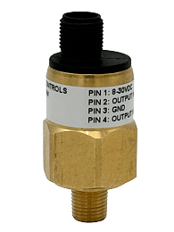




Solid State Pressure Sensor Electrical Status Indication
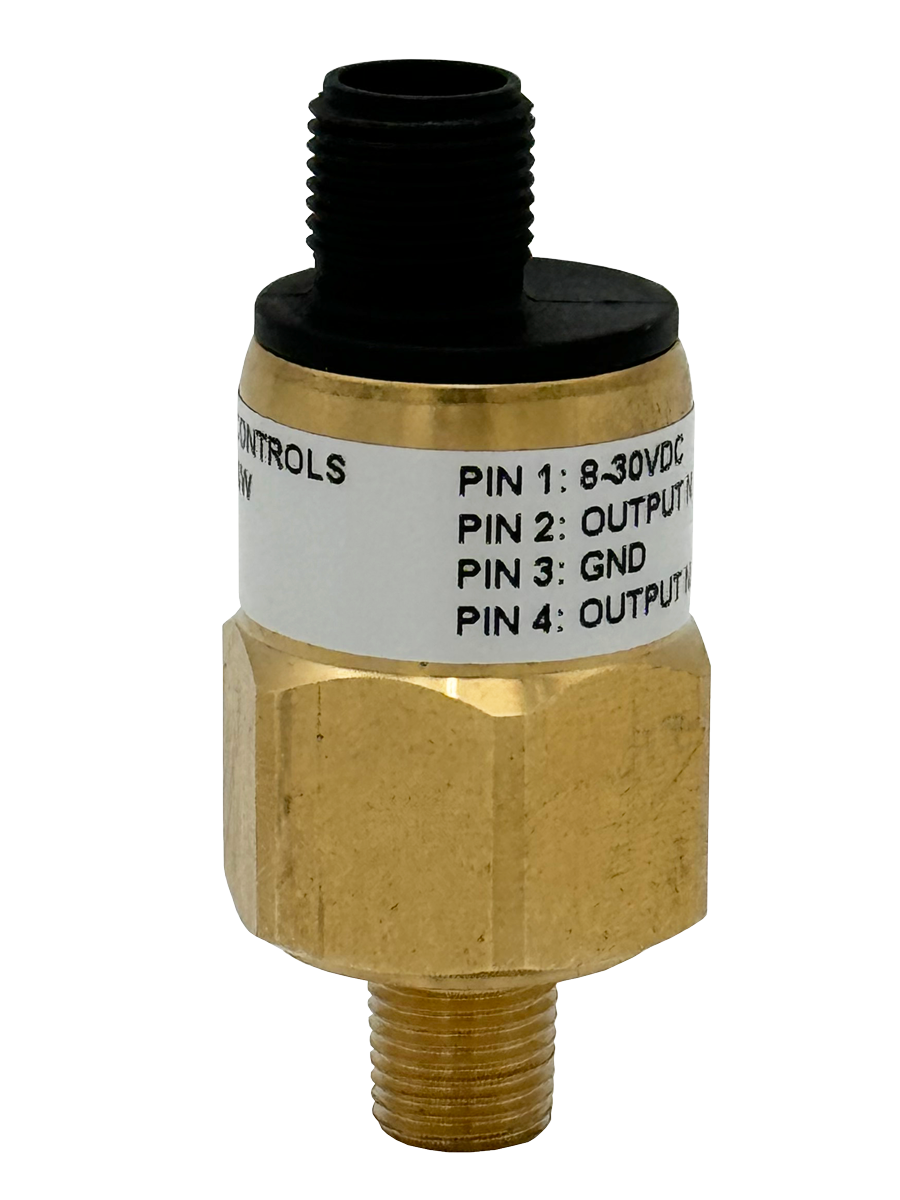
- May be installed on valves with an electrical status indication
- Provides status feedback to the control system indicating whether the valve is in the lockout or ready-to-run condition
- Factory preset, 17 psi (1.2 bar) - falling
loading...
loading...
Product Overview
The ROSS Controls solid state pressure sensors are electronic sensing devices that provide electrical status feedback to control systems indicating whether a pneumatic safety valve is in the lockout (isolated) or ready-to-run (pressurized) operating condition. Unlike mechanical pressure switches that use electromechanical contacts, the series sensors use solid-state switching technology with no moving mechanical parts, delivering improved reliability and extended operational life in high-cycle machine environments.
The primary application for Series sensors is as a status indicator on ROSS DM2 Series double valves and L-O-X lockout valves with electrical status indication sensing ports. The sensor is factory preset at 17 psi (1.2 bar) falling, providing a standardized switching threshold calibrated to the downstream pressure conditions of ROSS safety valve exhaust states. The M12 connection integrates directly with safety PLC M12 I/O modules, eliminating connector adapters.
The Series encompasses multiple sensor variants. The 1335B30W uses an M12 connector with M10 x 1 port thread. The Y766B94 is the designated DM2 Series C solid-state status indicator assembly with a built-in M12 connector, factory preset at 17 psi (1.2 bar) falling, specified directly within the DM2 Series C valve ordering table as status indicator code 2. A more capable 2447H77 digital pressure transducer is also available with dual PNP digital outputs and a 4-20 mA analog output for advanced monitoring applications.
Solid-state sensing eliminates the contact bounce, wear, and potential contact welding issues associated with mechanical switches, making the series sensors particularly well-suited for high-frequency machine cycles where contact reliability over millions of operations is critical to safety system integrity.
Key Engineering Features
- Solid-State Switching Technology - No mechanical contacts, eliminating contact wear, bounce, and welding failure modes common to electromechanical switches in high-cycle pneumatic applications.
- M12 Connector Interface - Built-in M12 connection integrates directly with safety PLC M12 I/O modules, M12 fieldbus devices, and 93 Series M12 wiring kits without adapters.
- Factory Preset at 17 psi (1.2 bar) Falling - Factory calibrated to close the output circuit when downstream pressure falls through 17 psi (1.2 bar), signaling the lockout/de-energized condition to the safety control system.
- PNP Digital Output Capability - Solid-state PNP transistor output compatible with the sinking input requirements of modern safety PLCs and safety relay input modules.
- Y766B94 DM2 Series C Status Indicator - Factory-integrated status indicator assembly specifically designed for DM2 Series C valve sensing ports, specified directly in the DM2 Series C ordering table as a built-in M12 connector assembly.
- 2447H77 Digital Transducer with Analog Output - Advanced variant with dual PNP digital outputs, 4-20 mA analog output, selectable operation modes (Easy, Window, Hysteresis), lockable keypad, and 12-24 VDC power input for comprehensive pressure monitoring applications.
- Multiple Engineering Unit Display (2447H77) - The 2447H77 transducer supports 6 pressure unit conversions including psi, bar, kPa, and other common industrial units for global application compatibility.
- No Calibration Required at Installation - Factory-preset models (1335B30W, Y766B94) are calibrated at the factory and require no field adjustment, reducing installation time and eliminating calibration errors.
- Long Service Life - Solid-state construction with no wearing mechanical contacts provides service life far exceeding electromechanical switches in high-cycle pneumatic applications.
- Small Form Factor - Compact housing dimensions allow direct installation into valve sensing ports without additional mounting hardware or piping adapters.
Technical Specifications
General Specifications
| Parameter | Specification |
| Sensor Type | Solid-state pressure sensor |
| 1335B30W Connection | M12 (built-in connector) |
| 1335B30W Port Thread | M10 x 1 |
| Y766B94 Connection | M12 (built-in connector) |
| Y766B94 Factory Preset | 17 psi (1.2 bar) falling |
| Y766B94 Application | DM2 Series C status indicator (status code 2) |
| 2447H77 Digital Outputs | Two PNP digital outputs (individually settable) |
| 2447H77 Analog Output | 4-20 mA |
| 2447H77 Power Supply | 12-24 VDC |
| 2447H77 Wiring | 5-pin female M12 connection |
| Operating Modes (2447H77) | Easy mode, Window mode, Hysteresis mode |
| Pressure Unit Display (2447H77) | 6 selectable pressure unit conversions |
| Keypad (2447H77) | Lockable keypad for tamper prevention |
Certifications & Compliance
Typical Applications & Industries
DM2 Series Safety Exhaust Double Valve Status Monitoring
- DM2 Series C double valve installations where the Y766B94 solid-state status indicator provides M12-connected electronic feedback of the valve exhaust state to a safety PLC or safety relay. The factory preset at 17 psi (1.2 bar) falling is calibrated to match the DM2 Series C exhaust pressure characteristics.
- Category 4 PLe press brake and press control systems where the solid-state status indicator Y766B94 provides the cross-monitoring diagnostic feedback required by ISO 13849 safety architecture requirements for control reliable double valve systems.
- High-speed stamping presses where mechanical pressure switch contacts would wear out before the scheduled maintenance interval due to high-cycle operation, making solid-state sensor technology the superior long-term reliability choice.
Lockout/Tagout Electronic Monitoring
- Networked lockout/tagout monitoring systems where 1335B30W sensors on multiple L-O-X valve sensing ports provide M12-connected digital inputs to a central safety PLC that monitors and logs energy isolation status across a complete production line.
- SCADA-integrated machine safety systems where the 4-20 mA analog output of the 2447H77 transducer provides continuous downstream pressure trending to the plant DCS for predictive maintenance and energy isolation audit documentation.
- Automated machine lockout verification systems where the safety PLC confirms receipt of the lockout status signal from all monitoring sensors before granting entry permission to the machine access zone.
Pneumatic Press and Metal Forming
- Metal stamping press pneumatic clutch/brake circuit monitoring where solid-state sensor technology provides reliable cycle-by-cycle status feedback without the mechanical contact degradation concerns associated with high-frequency mechanical switches.
- Automated press setup systems where the sensor provides the positive confirmation required to enable safe mode status signals for automated die transport and press adjustment routines.
- Transfer press lockout verification where M12 wiring infrastructure connects multiple Series sensors across press stations to a central safety controller without requiring individual DIN connector wiring runs.
Semiconductor and Electronics Manufacturing
- Cleanroom pneumatic system lockout monitoring where solid-state sensing eliminates particle generation from mechanical contact wear, maintaining the cleanliness requirements of Class 100 and ISO Class 5 cleanroom environments.
- Wafer handling equipment pneumatic lockout systems where the M12 connection integrates with the M12-based cleanroom fieldbus systems used in modern semiconductor equipment.
- Electronics assembly pneumatic actuator monitoring where high machine uptime requirements make solid-state sensor reliability a critical selection criterion over mechanical alternatives.
Industrial IoT and Predictive Maintenance
- Factory 4.0 implementations using the 2447H77 digital transducer with 4-20 mA analog output to stream continuous downstream pressure data to edge computing devices for valve performance trending and predictive maintenance scheduling.
- Connected machine monitoring where the 2447H77 Window mode monitors valve downstream pressure within an expected operating band, flagging deviations indicative of valve wear, partial seal failure, or downstream piping leaks.
- Energy monitoring programs where analog pressure output data quantifies compressed air consumption patterns at individual machine stations, supporting energy efficiency optimization initiatives.
Ordering and Model Number Configuration
For DM2 Series C valve stations, specify status indicator code 2 in the valve model number to receive the Y766B94 solid-state status indicator assembly with built-in M12 connection, factory preset at 17 psi (1.2 bar) falling.
The 1335B30W is a standalone solid-state sensor with M10 x 1 port thread and M12 connection. Verify the target valve has an M10 sensing port before ordering.
The 2447H77 digital pressure transducer is an advanced field-programmable device with dual digital and analog outputs. Order the 2431H77 wiring kit separately for a 5-meter M12 cable assembly, or the 2432H77 to receive the transducer with the wiring kit included.
For 93 Series M12 wiring system integration, use the M12 sensor connector kits (2644B77, 2645B77, etc.) to connect Series sensors to control panels and safety PLC M12 I/O.
When selecting between solid-state (Series) and mechanical (95 Series) pressure switches, consider: solid-state is preferred for high-cycle applications and modern M12 wiring systems; mechanical is appropriate for lower-cycle applications and existing DIN EN 175301-803 wiring infrastructure.
Related Products & Accessories
- 95 Series Mechanical Pressure Switches - Electromechanical pressure switches with DIN EN Form A and M12 connections for energy release verification where contact output is required. https://www.rosscontrols.com/en/series/95-mechanical-pressure-switches
- 94 Series Pop-Up Visual Indicators - Passive visual pressure indicator for physical energy release verification, complementary to electronic Series sensors. https://www.rosscontrols.com/en/series/94-pop-up-visual-indicators
- 93 Series Preassembled Wiring Kits - M12 sensor connector kits and complete wiring assemblies for connecting Series sensors to safety controllers and DM2 Series valve stations. https://www.rosscontrols.com/en/series/93-preassembled-wiring-kits
- DM2 Series Double Valves - Primary safety exhaust double valve series for which the Y766B94 solid-state status indicator is designed (status code 2). https://www.rosscontrols.com/en/series
- L-O-X Lockout Valves 15 Series - Manual lockout and exhaust valves with sensing ports for installation of Series sensors for electronic energy isolation monitoring. https://www.rosscontrols.com/en/series/1287-lockout-valves-15-series
Frequently Asked Questions (FAQ)
Q: What is the primary advantage of the series solid-state sensor over the 95 Series mechanical pressure switch?
A: Solid-state sensors have no mechanical contacts and no wearing parts in the switching mechanism, providing longer service life in high-cycle pneumatic applications. Mechanical contacts in the 95 Series pressure switches are subject to wear and eventual contact failure after millions of cycles. For machines cycling above 1 million times per year, solid-state sensing technology offers significantly improved reliability and reduced maintenance.
Q: What is the factory preset value for the Y766B94?
A: The Y766B94 DM2 Series C status indicator is factory preset at 17 psi (1.2 bar) falling. The switch output transitions when downstream pressure drops through 17 psi, signaling the lockout or valve-exhausted condition to the safety controller.
Q: What is the difference between the Y766B94 and the 1335B30W?
A: The Y766B94 is specifically engineered as a DM2 Series C status indicator assembly with a built-in M12 connector calibrated at 17 psi (1.2 bar) falling. It is ordered as part of the DM2 Series C valve configuration (status code 2). The 1335B30W is a standalone solid-state sensor with M10 x 1 port thread for installation in the sensing ports of other ROSS valve series. The 1335B30W factory preset value should be confirmed with ROSS for the specific application.
Q: What is the 2447H77 digital pressure transducer and when should I use it?
A: The 2447H77 is an advanced multi-function digital pressure transducer with dual PNP digital outputs and a 4-20 mA analog output. Use it when continuous pressure monitoring, proportional pressure output for DCS integration, or field-adjustable switching thresholds are required. It supports three operation modes and displays in 6 pressure units. Use factory-preset 1335B30W or Y766B94 for standard on/off status monitoring applications where continuous pressure trending is not needed.
Q: What PLC input type do the digital outputs of the series sensors use?
A: The digital outputs are PNP (sourcing) type, switching the output high (to supply voltage) when active. The safety PLC or input module must accept PNP discrete inputs. Verify the input type of the safety controller before specifying Series sensors in the control system design.
Q: Can the series sensors be used with safety relay inputs directly?
A: Verify the safety relay's input specification. Most dual-channel safety relays accept either PNP or NPN inputs. The PNP solid-state output of the series must match the relay's input polarity requirement. For safety relays requiring dry contact (potential-free) inputs, the mechanical pressure switch 95 Series with contact output is the appropriate choice.
Q: What wiring kit should I use with the 2447H77 transducer?
A: Order the 2431H77 5-meter M12 wiring kit for the cable assembly, or the 2432H77 which includes both the transducer and wiring kit as a complete assembly. The 5-pin female M12 connector on the 2447H77 accepts the standard 5-pin M12 male connector on these wiring kits.
Q: How do I configure the 2447H77 switching thresholds?
A: The 2447H77 uses a front panel keypad for threshold configuration. In Easy mode, set one switching point with the hysteresis band. In Window mode, set upper and lower band limits. In Hysteresis mode, set independent switch-on and switch-off points. The keypad can be locked after configuration to prevent unauthorized changes. Refer to the 2447H77 instruction manual available from ROSS Controls for detailed configuration procedures.
Q: Is the series compatible with fieldbus systems?
A: The factory-preset sensors (1335B30W, Y766B94) provide discrete M12 digital outputs compatible with any discrete I/O system. The 2447H77 provides both digital M12 outputs and 4-20 mA analog output. For direct integration with AS-Interface, IO-Link, Profibus, or EtherNet/IP field buses, contact ROSS Controls for available connectivity options.
Q: Can the series sensor be tested for correct function in the field?
A: Yes. With the sensor installed and the system powered, use a pressure gauge or the 2447H77 display to monitor the downstream pressure while the valve is cycled. Confirm the sensor output state changes at the expected preset threshold value. The 94 Series Pop-Up Visual Indicator installed at the same sensing location provides visual cross-verification of the sensor's electronic output.
Q: What is the difference between using the solid-state sensor (code 2) versus the mechanical pressure switch (code 1) as a DM2 status indicator?
A: Status code 1 (mechanical pressure switch Y670B94) uses electromechanical contacts with DIN EN 175301-803 Form A or M12 connection. Status code 2 (solid-state sensor Y766B94) uses a PNP solid-state output with built-in M12 connection. For modern safety PLCs with M12 I/O, code 2 provides a direct M12 interface. For existing DIN EN connector wiring infrastructure or safety relay dry contact inputs, code 1 may be preferred.
Q: What is the M10 port thread on the 1335B30W?
A: M10 x 1 is a metric thread (10 mm diameter, 1 mm pitch) used on the compact sensing port of the 1335B30W sensor. This thread type is used on specific ROSS valve sensing ports designed to accept M10-threaded sensors. Verify the valve sensing port thread specification from the valve data sheet before ordering the 1335B30W.
Installation & Maintenance Guidelines
- Install the 1335B30W by threading the M10 x 1 port into the valve sensing port. Torque to manufacturer specifications to avoid over-tightening and damage to the sensor body.
- For Y766B94 on DM2 Series C valves, the sensor assembly is integrated into the valve station as a factory option. Follow DM2 Series installation instructions for proper mounting and wiring.
- Connect the M12 sensor output to the safety PLC or monitoring system I/O module using M12 sensor cables from the 93 Series (2644B77 or 2645B77) or equivalent M12 cable assemblies.
- For the 2447H77 digital transducer, connect the 5-pin M12 cable per the wire assignment table. Power supply must be 12-24 VDC. Configure the switching threshold using the front panel keypad or via the Easy mode default configuration.
- Lock the 2447H77 keypad after configuration to prevent unauthorized setpoint changes in production environments.
- After installation, verify sensor operation by pressurizing the downstream circuit above the preset threshold and confirming the digital output state, then exhausting pressure and confirming the output changes state at the preset threshold.
Warranty & Global Support
ROSS Controls provides a one-year warranty on all Series Solid State Pressure Sensors, covering defects in material and workmanship from date of purchase.
Technical support is available at Customer Service: 1-800-GET-ROSS; Technical Service: 1-888-TEK-ROSS.
Data sheets for all Series models including wiring diagrams and configuration instructions are available at rosscontrols.com.
Download Catalog: https://www.rosscontrols.com/en/series/2854-solid-state-pressure-sensor
Download Documents
Solid State Pressure Sensor